I’m looking for four resistors for two single under blanket heaters.
Please can you read off and report the colour codes? I can see the red stripe, but the darker colours are a bit ambiguous to me: possibilities include black, blue, green, brown. We’re looking for the sequence of three colours, from left to right, of each of the two. (The silver band is easy enough to read - that means it’s a 10% tolerance device.)
If you can measure the length too, that might help - these resistors are probably a bit larger than the usual, to dissipate more heat.
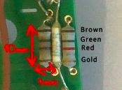
Thanks Ed. Just in case you can’t read measurements, 10mm x 4mm
By the way, only 7 days left before ‘FREE’ trip to the ‘MOON’ closes.
Lovely job: Brown Green Red is 1k5 Ohms or 1.5 kOhms in old money. But are both resistors the same colour sequence? It didn’t look like it to me. If the other one is Brown Green Brown then that’s just 150 Ohms, and it would be important to put the right replacement in the right place.
(Having said that, I would guess that a failed resistor will usually look fire-damaged.)
It looks to me like the one resistor has a silver band but the other has a gold bank, so that’s a higher accuracy resistor. Resistors are cheap enough, but it’s unlikely that anyone would have an exact replacement on hand, so postage costs are likely to dominate.
One quick note, & I’m not certain in this:
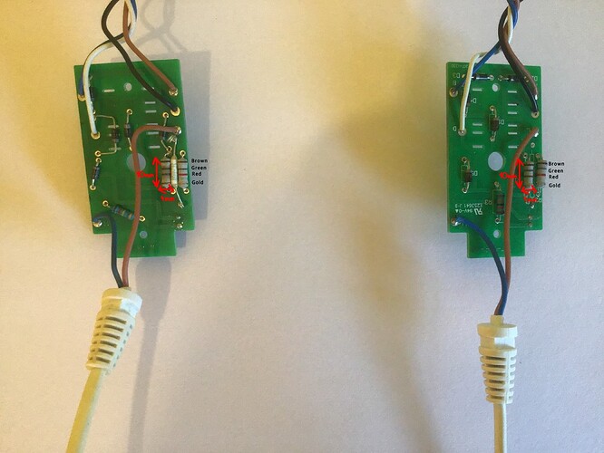
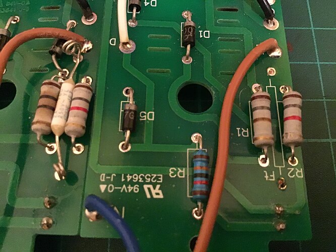
Seeing the second pic (the board on the left), it looks like (probably) a thermal fuse in between the resistors. If it is, then that should fail before the resistors would, so might be what’s gone (or may need replacing as well).
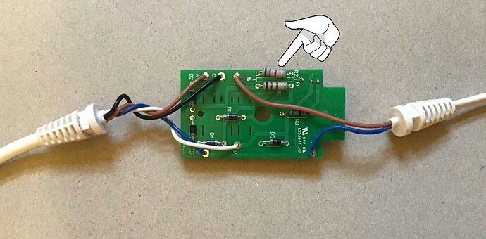
The first pic has that area empty, but marked with Ft . F is a designator for fuse, but I can’t find info on where t is for thermal.
The markings on the component been the resistors might confirm what it is.
Example of something similar (but could be s different rating)
https://www.ebay.co.uk/itm/5Pcs-FUJI-Microtemp-Thermal-Fuse-Axial-102-TF-Cutoff-2A-250V-FTF-2-Type-298-/181691160421
Oh, well spotted! So, on the one board, the thermal fuse has blown itself away entirely? It would make good sense, to have such a fuse right next to the resistors, to sense excessive current.
It might be, then, that the fuse has acted as the safety measure it’s meant to be, and that particular blanket should be regarded as dangerously shorted.
I’ve had a closer then closer look, (is that possible?) they are both: Brown Green Red Gold.
Thanks Will, by the way, the blankets are both the same brand and model numbers (Volt 220-240-Watt 90). One has a thermal fuse and one doesn’t?
Forgot to add link for ‘moon’ trip on previous comment, five days left.
https://www.reuters.com/article/us-japan-maezawa-moon-idUSKCN2AU2QB
I’m looking at the left one here and not seeing red:
But perhaps you already have a reason to think that one particular component is blown?
The left fuse is blown, it should be the same colours as its twin on the right.
Hee hee, there are two lefts and rights. On the one hand, you posted a photo with two boards, and on the other hand, each board has two large resistors. So, four resistors in total, and of each pair, the right one looks to me like it has a red stripe and the left of the pair doesn’t.
But also, we’re now noting that the left board has a thermal fuse, in between the two resistors, and the right board doesn’t. Although there are two holes for a fuse, and a legend on the board, there’s no visible sign of a fuse ever having been there.
(I’d also note that the two boards differ: they both have, I think, 5 diodes, but not in the same arrangement.)
Anyhow, back to your first post, you say you want to replace both resistors on both boards, four in total. So, it does matter what the colour codes are, of all four. If you really are saying that all four resistors have a red stripe, can you post a photo which shows that?
Sorry to be full of cross-examination!
It’s worth figuring out what caused the problem. This person (in the article linked below) found that one of the diodes had shorted. Also found that it’s difficult to solder a thermal fuse without blowing it. It seems to me that the point of the resistors is to dissipate some heat which the thermal fuse detects, so the fuse needs to be mounted close to the resistors to do its job. I see your thermal fuse has long leads, coiled for compactness, so the soldering heat needn’t reach the fuse.
The article reckons the resistors are half-watt but maybe they are 3 watt. Oddly enough, the two resistors there are the same values as each other, unlike yours…
(Just a thought: do you have trouble distinguishing colours?)
I found a patent, which indicates that the four wires going to the blanket are two for the heater and two for a sacrificial overheat sensor wire. The resistors, then, would in series with the sensor wire. (But it would still be worthwhile to trace out the circuit diagram, I think.)
That’s good detective work.
I got stuck when
- None of the repair vids I found on YouTube we’re for similar blankets
- The number on the board just got loads of hits for a controller board for a treadmill!
It might need photos of both sides to figure out all of the traces & do a BigClive circuit diagram - as you say @Ed_S, a circuit diagram is worthwhile to help sanity check in case there are other failure on the board.
Might be worth checking components with a multimeter if you have one @Laurentius (there’s one in the Techshed cupboard once lockdown’s over)
Thanks chaps, to be continued…


